Hello Everybody,
I'm new to this field as well as in CNC machining and I have a misunderstanding, let me explain
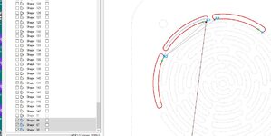
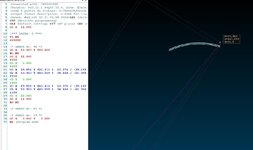
I'm trying to make a rounded machining of the width of my tool and when I export my toolpath it gives me the contour of my machining, So I've got a lot more machining to do than I'd like, I don't understand, could you tell me where is the problem?.
Thank's a lot for your answers
Below is the code generated by DXF2GCODE
(Generated with: DXF2GCODE)
(Version: Py3.11.1 PyQt5.15.8, Date: [imath]Date: Mon Feb 6 21:49:45 2023 +0100[/imath])
(Créé à partir du fichier: G:/Test.DXF)(Used Postprocessor: postpro_config.cfg)
(Output format description: G-CODE for LinuxCNC)
(Heure: Mon Oct 28 13:16:40 2024)G21 (Units in millimeters)
G90 (Absolute programming)
G64 (Default cutting) G17 (XY plane) G40 (Cancel radius comp.) G49 (Cancel length comp.)
G0 Z 15.000
(*** LAYER: 0 ***)
T1 M6
S10000
(* SHAPE Nr: 67 *)
G0 X 24.684 Y 30.153
M3
G0 Z 12.000
F150
G1 Z 7.000
F400
G2 X 25.805 Y 60.915 I 39.613 J 13.958 (why does it generate multiple lines?)
G2 X 28.554 Y 59.715 I 1.375 J -0.600
G3 X 27.513 Y 31.150 I 35.742 J -15.604
G2 X 24.684 Y 30.153 I -1.415 J -0.498
F150
G1 Z 6.000
F400
G2 X 25.805 Y 60.915 I 39.613 J 13.958
G2 X 28.554 Y 59.715 I 1.375 J -0.600
G3 X 27.513 Y 31.150 I 35.742 J -15.604
G2 X 24.684 Y 30.153 I -1.415 J -0.498
F150
G1 Z 5.000
F400
G2 X 25.805 Y 60.915 I 39.613 J 13.958
G2 X 28.554 Y 59.715 I 1.375 J -0.600
G3 X 27.513 Y 31.150 I 35.742 J -15.604
G2 X 24.684 Y 30.153 I -1.415 J -0.498
F150
G1 Z 4.000
F400
G2 X 25.805 Y 60.915 I 39.613 J 13.958
G2 X 28.554 Y 59.715 I 1.375 J -0.600
G3 X 27.513 Y 31.150 I 35.742 J -15.604
G2 X 24.684 Y 30.153 I -1.415 J -0.498
F150
G1 Z 3.000
F400
G2 X 25.805 Y 60.915 I 39.613 J 13.958
G2 X 28.554 Y 59.715 I 1.375 J -0.600
G3 X 27.513 Y 31.150 I 35.742 J -15.604
G2 X 24.684 Y 30.153 I -1.415 J -0.498
F150
G1 Z 2.000
F400
G2 X 25.805 Y 60.915 I 39.613 J 13.958
G2 X 28.554 Y 59.715 I 1.375 J -0.600
G3 X 27.513 Y 31.150 I 35.742 J -15.604
G2 X 24.684 Y 30.153 I -1.415 J -0.498
F150
G1 Z 1.000
F400
G2 X 25.805 Y 60.915 I 39.613 J 13.958
G2 X 28.554 Y 59.715 I 1.375 J -0.600
G3 X 27.513 Y 31.150 I 35.742 J -15.604
G2 X 24.684 Y 30.153 I -1.415 J -0.498
F150
G1 Z 0.000
F400
G2 X 25.805 Y 60.915 I 39.613 J 13.958
G2 X 28.554 Y 59.715 I 1.375 J -0.600
G3 X 27.513 Y 31.150 I 35.742 J -15.604
G2 X 24.684 Y 30.153 I -1.415 J -0.498
F150
G1 Z 12.000
G0 Z 15.000
G0 X 0.000 Y 0.000
M30 (Program end)
Anhänge
Zuletzt bearbeitet:


